LED Guide: Types, Colors, Voltages, and How to Calculate the Resistor
Every technician has burned out an LED in a rush at some point. You plug it directly into the bench power supply just to “see if it lights up”—you get that beautiful flash, and then permanent silence. The LED is one of the simplest components out there and, at the same time, one of the ones that raises the most questions when it comes to calculations: why does blue need more voltage than red? Can you swap a yellow LED for a white one in the same circuit? Which resistor should you use at 12 V? Why does that hastily repaired LED strip burn out again in a week?
This guide answers these questions with ready-to-use reference tables—voltage and current by color, package comparisons, and pre-calculated resistor values for 3.3 V, 5 V, 9 V, 12 V, and 24 V—and explains the basics of physics you need to know so you don’t have to rely on any tables at all. At the end, there’s a bench-test diagnostic checklist and the complete guide available for download as a PDF.
1. Why Color Determines Voltage
An LED (Light Emitting Diode) is, first and foremost, a diode: it conducts in one direction and blocks in the other. The difference from a standard rectifier diode lies in the material of the semiconductor crystal. While silicon releases almost all of the energy from electron-hole recombination as heat, the compounds used in LEDs—gallium arsenide, aluminum-indium-gallium phosphide, indium-gallium nitride—emit this energy as photons, that is, as light.
The most important practical consequence is that color and forward voltage arise together from the same physical phenomenon. The energy of a photon is inversely proportional to its wavelength: the bluer the light, the more energy per photon, and therefore the higher the potential barrier the electron must overcome. That is why a red LED lights up at 1.8 V while a blue one requires 3.2 V—it’s not a choice made by the manufacturer; it’s the physics of the material.
This same reasoning explains a curious fact that confuses many people: a white LED has exactly the same voltage as a blue one. It is actually a blue LED with a layer of yellow phosphor deposited on the chip. The phosphor converts part of the blue light into yellow, and the mixture of the two appears white to the eye. When a white LED “yellows” over time, it is this phosphor layer that has deteriorated, usually due to excessive current.
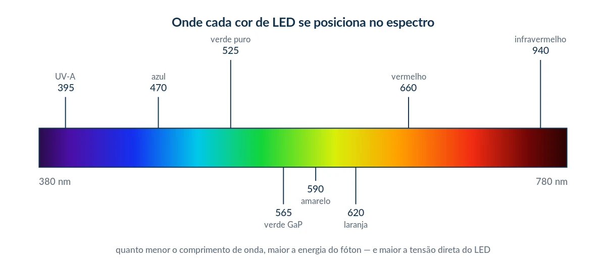
fig-espectro-led.png — alt: "Visible spectrum showing the position of each LED color, from UV-A to infrared"
An LED is not a resistor
The second consequence is equally practical. The LED’s characteristic curve is exponential: below the knee voltage, virtually no current flows, and a few tenths of a volt above it, the current skyrockets. An increase of 0.1 V can double the current.
This means that connecting an LED directly to the power source, without any limiting element, supplies it with all the current the source is capable of providing. Every circuit with an LED must have a limiting element: a resistor, in simple cases, or a constant-current driver, for power LEDs. With LEDs, you control the current, never the voltage.
2. How to Identify Polarity—Three Methods
The 5-mm DIP package remains the bench standard. Inside the epoxy capsule is a conical reflector (the cup) where the chip is seated, a very fine gold wire (bond wire) connecting the top of the chip to the opposite terminal, and the epoxy lens, which defines the beam angle—from 15° in narrow-beam LEDs to 120° in wide-beam LEDs.
It’s worth knowing the three ways to identify polarity, because with used components or those with the leads already cut, the first method doesn’t always work:
Longer leg = anode (+). This is the quick method, and the first one to be lost when someone cuts the leads.
Chamfered side of the capsule = cathode (−). The marking that survives when the leads are cut.
Hold it up to the light. The foolproof method: the larger metal part—the reflector on which the chip rests—is the cathode.
When testing with a multimeter set to the diode scale, touching the red probe to the anode causes the LED to glow faintly and displays the forward voltage on the screen—a good LED shows a reading between 1.6 V and 3.2 V, depending on the color.
3. Indicator LEDs by Color — Voltage and Current
The table lists the most common indicator LEDs in 3-mm and 5-mm DIP packages, which are the ones found in any bench drawer. The forward voltage values are typical ranges at 20 mA and room temperature. Parts from the same batch vary from one another, and parts from different manufacturers vary even more: whenever the project is a production run or involves many units, measure a sample rather than relying on the table.
Color | Wave Compression | Material | Typical VF | Max. VF | Typical IF | Max. IF |
|---|---|---|---|---|---|---|
Infrared | 850–940 nm | GaAs | 1.2–1.6 V | 1.8 V | 20 mA | 50–100 mA |
Red | 620–660 nm | AlGaAs / GaAsP | 1.8–2.2 V | 2.4 V | 20 mA | 30 mA |
Orange | 605–620 nm | AlGaInP | 2.0–2.2 V | 2.5 V | 20 mA | 30 mA |
Amber | 590–605 nm | AlGaInP | 2.0–2.3 V | 2.5 V | 20 mA | 30 mA |
Yellow | 585–590 nm | GaAsP | 2.1–2.4 V | 2.6 V | 20 mA | 30 mA |
Traditional green | 560–570 nm | GaP | 2.0–2.4 V | 2.6 V | 20 mA | 30 mA |
Pure green | 520–535 nm | InGaN | 3.0–3.4 V | 3.8 V | 20 mA | 30 mA |
Blue | 460–475 nm | InGaN | 3.0–3.4 V | 3.8 V | 20 mA | 30 mA |
Cool white | 6,000–8,000 K | InGaN + phosphor | 3.0–3.4 V | 3.8 V | 20 mA | 30 mA |
Warm white | 2700–3500 K | InGaN + phosphor | 3.0–3.3 V | 3.8 V | 20 mA | 30 mA |
Violet | 400–410 nm | InGaN | 3.1–3.5 V | 4.0 V | 20 mA | 30 mA |
UV-A (black light) | 365–395 nm | InGaN | 3.2–3.8 V | 4.2 V | 20 mA | 30 mA |
UV-C (germicidal) | 265–285 nm | AlGaN | 5.0–7.0 V | 8.0 V | 20–100 mA | per manufacturer |
RGB | 3 chips | mixed | R 2.0 / G 3.2 / B 3.2 | 3.8 V | 20 mA/color | 30 mA/color |
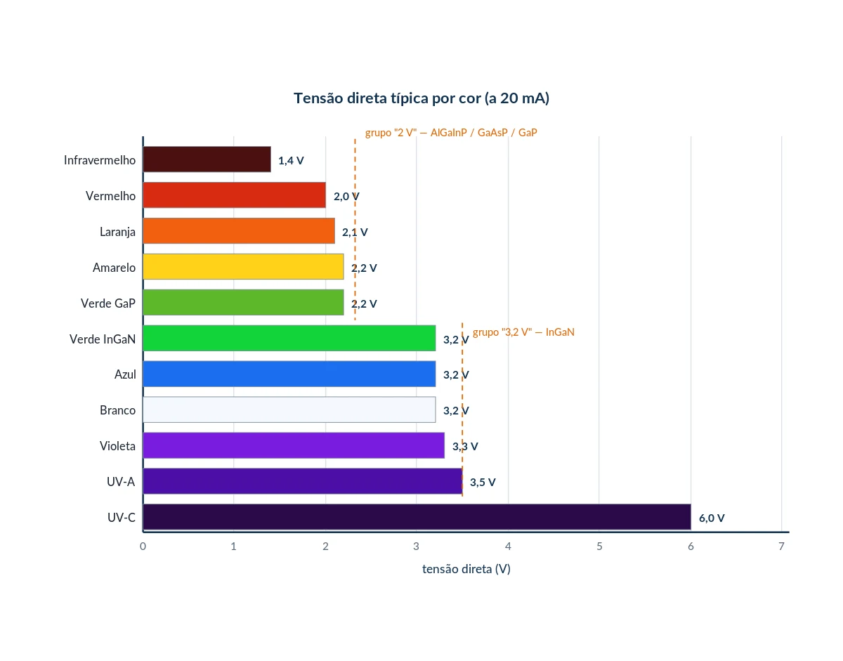
fig-voltage-by-color.png — alt: "Graph of forward voltage by color showing the 2 V and 3.2 V groups"
The Rule of Three Numbers
Looking at the graph, it’s clear that the LEDs aren’t scattered across the voltage scale—they cluster together. And that’s what lets you work by memory at the bench.
2 V group — red, orange, amber, yellow, and traditional green (AlGaInP, GaAsP, GaP).
3.2 V group — pure green, blue, white, violet, and UV-A (all InGaN).
Infrared — isolated at 1.4 V.
Remembering these three numbers solves 95% of the calculations without consulting any tables. In practice, this rule also answers the question of swapping colors: you can swap a red for a yellow without recalculating anything, but swapping for a blue or white requires adjusting the resistor—the 1.2 V difference is entirely accounted for by the voltage drop across the resistor.
4. Packages: DIP, SMD, and COB
The package does not alter the chip’s physics, but it defines almost everything else: how much current the component can handle, how much heat it can dissipate, what the beam angle is, and how it is mounted. The same 3.2 V blue chip can be housed in a 5 mm DIP package consuming 20 mA or in a ceramic package with a heat sink consuming 1 A—what changes is the ability to remove heat from near the junction.
A time-saving tip: the numerical code for SMDs is always width × length in tenths of a millimeter. 3528 = 3.5 × 2.8 mm; 5050 = 5.0 × 5.0 mm. Knowing this, you can identify the component with a caliper, without needing the datasheet.
Code | Dimensions | Chips | Power | VF | IF | Typical Application |
|---|---|---|---|---|---|---|
0603 / 0805 / 1206 | 1.6×0.8 to 3.2×1.6 | 1 | 0.06 W | color-coded | 5–20 mA | Panel display |
3014 | 3.0 × 1.4 mm | 1 | 0.1 W | 3.0–3.2 V | 30 mA | LED strip, backlight |
3528 (PLCC-2) | 3.5×2.8 mm | 1 | 0.08 W | 3.0–3.4 V | 20 mA | 12 V strip, 60 LEDs/m |
2835 | 2.8×3.5 mm | 1 | 0.2–1 W | 3.0–3.4 V (or 9 V / 18 V) | 60–300 mA | Lamps, panels |
5050 (PLCC-6) | 5.0×5.0 mm | 3 | 0.24 W | 3.0–3.4 V/chip | 20 mA/chip | RGB strip |
5730 | 5.7×3.0 mm | 1 | 0.5–1 W | 3.0–3.4 V | 150–300 mA | High-flux LEDs |
WS2812B | 5.0×5.0 mm | 3 + IC | 0.3 W | 5.0 V (power supply) | ~60 mA (white) | Addressable strip |
Cabochon / Diffused | 3–10 mm | 1 | 0.06 W | depending on color | 20 mA | Front panel |
Power LEDs
Starting at approximately 0.5 W, a resistor is no longer an acceptable solution: it would dissipate more energy than the LED itself and, worse, would not protect the component from thermal runaway. In such cases, a constant-current driver is used, and the heat sink becomes a design element rather than an accessory. The rule of thumb is simple: a power LED without a heat sink has a lifespan measured in seconds.
Type | Power | VF | IF | Typical Luminous Flux | Note |
|---|---|---|---|---|---|
1 W Power LED | 1 W | 3.0–3.4 V (white) / 2.2–2.6 V (red) | 300–350 mA | 90–130 lm | Heat sink of at least 10 cm² |
3 W Power LED | 3 W | 3.2–3.6 V | 700 mA | 200–260 lm | Heat sink required |
5 W Power LED | 5 W | 3.2–3.8 V | 1.0–1.5 A | 350–450 lm | Constant-current driver |
Cree XP-G / XM-L | 3–10 W | 2.9–3.5 V | 0.7–3 A | 280–1,000 lm | Flashlights, high efficiency |
COB 10–50 W | 10–50 W | 9–12 V or 30–34 V | 0.3–1.5 A | 800–4,500 lm | Internal series/parallel array |
220 V module (driverless) | 5–50 W | rectified mains | internal | variable | Common in lamps and floodlights; uninsulated circuit |
Caution with driverless modules. Modern lamp and reflector boards connect the LEDs in series directly to the rectified mains supply. The entire circuit is at mains potential, with no galvanic isolation. Never measure, touch, or handle one of these boards while it is energized—even the aluminum heat sink may be live.
5. Calculating the current-limiting resistor
The series resistor solves the current problem in an elegant way: the difference between the supply voltage and the LED’s forward voltage drops across it, and this difference divided by the desired current gives the resistance value.
R = (VSOURCE − VF) ÷ IF | PR = (VSOURCE − VF) × IF
Current is always in amperes: 20 mA = 0.020 A.
Since the voltage drop across the resistor is linear and that across the LED is practically fixed, the circuit stabilizes itself. And there’s one detail that almost no one mentions: the greater the excess voltage across the resistor, the more stable the circuit becomes. That’s why powering a 3.2 V LED with 12 V yields much more predictable results than powering it with 3.3 V—in the latter case, there’s a 0.1 V surplus, and any variation in batch or temperature visibly changes the brightness.
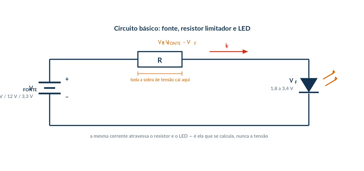 fig-circuit-resistor.png — alt: "Circuit with power supply, current-limiting resistor, and LED, with voltages labeled"
Pre-set values for the most common power supplies
Power Supply | Desired | Desired I | Calculation | Commercial R | Power dissipated | Resistor |
|---|---|---|---|---|---|---|
3.3 V | Red (2.0 V) | 10 mA | 1.3 ÷ 0.010 = 130 Ω | 130 Ω | 13 mW | 1/8 W |
3.3 V | White/Blue (3.2 V) | — | 0.1 V to spare | not feasible | — | Use a boost converter |
5 V | Infrared (1.4 V) | 20 mA | 3.6 ÷ 0.020 = 180 Ω | 180 Ω | 72 mW | 1/8 W |
5 V | Red (2.0 V) | 20 mA | 3.0 ÷ 0.020 = 150 Ω | 150 Ω | 60 mW | 1/8 W |
5 V | Yellow/Green (2.2 V) | 20 mA | 2.8 ÷ 0.020 = 140 Ω | 150 Ω | 56 mW | 1/8 W |
5 V | White/Blue (3.2 V) | 20 mA | 1.8 ÷ 0.020 = 90 Ω | 100 Ω | 36 mW | 1/8 W |
9 V | Red (2.0 V) | 20 mA | 7.0 ÷ 0.020 = 350 Ω | 390 Ω | 140 mW | 1/4 W |
9 V | White/Blue (3.2 V) | 20 mA | 5.8 ÷ 0.020 = 290 Ω | 330 Ω | 116 mW | 1/4 W |
12 V | Red (2.0 V) | 20 mA | 10.0 ÷ 0.020 = 500 Ω | 560 Ω | 200 mW | 1/4 W |
12 V | Yellow/Green (2.2 V) | 20 mA | 9.8 ÷ 0.020 = 490 Ω | 560 Ω | 196 mW | 1/4 W |
12 V | White/Blue (3.2 V) | 20 mA | 8.8 ÷ 0.020 = 440 Ω | 470 Ω | 176 mW | 1/4 W |
12 V | 3 × White in series (9.6 V) | 20 mA | 2.4 ÷ 0.020 = 120 Ω | 120 Ω | 48 mW | 1/8 W |
24 V | Red (2.0 V) | 20 mA | 22.0 ÷ 0.020 = 1100 Ω | 1.2 kΩ | 440 mW | 1 W |
24 V | 6 × White in series (19.2 V) | 20 mA | 4.8 ÷ 0.020 = 240 Ω | 270 Ω | 96 mW | 1/4 W |
Always round up the resistor value. A resistor higher than the calculated value means a slightly lower current—the LED will glow a little less brightly but will last much longer. A smaller resistor means current above the specified level, junction heating, and accelerated degradation of the phosphor—which is what causes white LEDs to turn yellow. When in doubt, for panel indicators, 10 mA is more than enough and practically doubles the service life.
6. Series and Parallel — The Classic Mistake
Connecting LEDs in series is almost always the best choice: the same current flows through all of them, the brightness is uniform, and a single resistor is sufficient for the entire array. The limiting factor is the available voltage—the sum of the forward voltages must leave at least 15% to 20% of the supply voltage available for the resistor, or the circuit becomes too sensitive to temperature and batch variations.
Connecting LEDs in parallel and sharing a single resistor is the classic mistake, and it’s worth understanding why it’s so treacherous. Since the forward voltage varies between units, the one with the lowest VF conducts more current, heats up, has its VF reduced even further by the negative temperature coefficient, conducts even more current—and burns out. After that, the others receive the full current and follow the same path, one by one. The circuit works on the bench but fails the following week.
The solution is simple: one resistor for each branch. This is, by far, the most common cause of burned-out LEDs in hastily repaired strips and panels.
7. Practical Bench Notes
Dimming
Reducing the voltage to dim an LED doesn’t work: below a certain threshold, it simply turns off, and the usable range between “off” and “full brightness” is only a few tenths of a volt. The correct method is PWM—maintain the rated current and vary the on-time. Frequencies above 200 Hz are already imperceptible to the eye; for lighting in environments with cameras, use frequencies above 2 kHz to avoid flickering in the video.
One detail that often trips up programmers: the eye responds logarithmically. A 50% duty cycle does not appear to be half the brightness, but rather closer to 70%. If the result in the firmware is “without a middle ground,” what’s missing is a gamma correction curve, not more PWM resolution.
Effect of Temperature
The forward voltage drops by approximately 2 to 4 mV per degree Celsius increase at the junction. In an indicator LED with a resistor, this is irrelevant. In a power LED powered by a fixed-voltage source, it is fatal: heating reduces VF, which increases the current, which increases the heating—the so-called thermal runaway. Hence the rule that power LEDs require a constant-current driver, not a constant-voltage driver.
Quick Diagnosis
Symptom | Most Likely Cause | Check |
|---|---|---|
Does not light up | Reverse polarity or open resistor | Diode range: A good LED shows 1.6–3.2 V and glows dimly |
Glows very dimly | Resistor value too high or power supply voltage drop | Measure the voltage across the resistor and divide by its value |
Burned out in seconds | No current limiting | Check if there is a resistor in the branch |
Turned yellow / lost its luster | Chronic overcurrent; degraded phosphor | Measure the actual current and compare it to the rated current |
One on the strip is off, the others are on | SMD shorted or cold solder joint | A temporary jumper on the suspect LED restores the segment |
Entire strip is out starting from a certain point | Open SMD in series | Check continuity segment by segment |
Flickering | Driver filter capacitor is dry | Visual inspection and ESR measurement of the electrolytic capacitor |
Pre-energization checklist
Is there a resistor or driver limiting the current in each branch?
Is the polarity correct—do the long leg, bevel, and reflector point in the same direction?
Does the sum of the VF values in series leave a margin for the resistor?
Is the resistor’s power rating at least twice the calculated value?
For power ratings above 0.5 W, is there a heat sink with thermal paste?
Download the complete guide as a PDF
All the content in this article is available in an 8-page A4 guide, formatted for printing and reference at the workbench, with six vector illustrations: I×V characteristic curve, cross-sectional view of an LED, voltage-by-color chart, real-scale comparison of packages, current-limiting resistor circuit, and the three side-by-side connection topologies.
Download the guide as a PDF — 8 pages
Bits e Bytes Eletrônica e Informática is based in Belém, Pará, offering authorized multi-brand technical support and systems development. If you have a device with a lighting, backlight, or LED board issue, contact us.
The values shown are typical market values. For production projects, always check the datasheet from the specific component manufacturer.
What did you think?
Related Posts

Comments
Comments are moderated before being published.